The lower structure of heavy digging equipment accounts for roughly 20% of the machine's initial purchase price. However, it consumes up to 50% of its lifetime maintenance budget. Unplanned downtime and accelerated component degradation frequently occur on job sites. Operators and fleet managers often misunderstand the mechanical limits, maintenance cycles, and wear patterns of their track systems. A deep technical understanding of how the system operates remains a prerequisite for success. You must accurately diagnose wear and evaluate replacement options to reduce long-term operating expenses. When you grasp the mechanics of the excavator undercarriage system, you prevent catastrophic failures. The structural integrity of these lower components dictates the efficiency, safety, and operational lifespan of the entire machine.
The excavator undercarriage system operates as a closed continuous loop track system driven by high-torque axial piston hydraulic motors, requiring precise tensioning to function efficiently.
Selecting the correct excavator track shoes and roller configurations must be dictated by specific terrain and load requirements to prevent premature structural fatigue.
Proactive daily inspection of the tensioning system (idler and recoil spring), drive mechanisms, and guide wheels prevents catastrophic chain failures.
Sourcing replacement construction machinery wear parts requires evaluating material hardness, heat treatment depth, and compatibility rather than competing on initial price alone.
Core Functionality: How the Excavator Undercarriage System Works
Weight Distribution and Operational Stability
The lower frame design distributes the machine's massive operating weight evenly across its entire footprint. This high-flotation stability contrasts sharply with the mobility-focused design of wheeled undercarriages. Tracked systems excel in soft soil, deep mud, and rugged terrain. They provide a massive surface area to lower ground bearing pressure, often reducing the machine's footprint pressure to less than that of a human foot. This prevents the equipment from sinking in marshy or uncompacted environments.
The mechanical requirements for supporting the upper structure are immense. The central carbody, built with a heavy-duty X-frame design, sustains the excavator during 360-degree rotation. It handles heavy dynamic loads and uneven terrain without twisting or fracturing. High-tensile steel plates are welded into a box-section design to resist torsional stress when the machine digs over the side of the tracks. The slewing ring mounting pad sits at the center of this X-frame, providing a perfectly flat, machined surface for the swing bearing. Structural integrity here ensures the machine remains balanced while lifting heavy materials. The side track frames weld directly to this central carbody to hold the rolling components in strict, unyielding alignment.
Propulsion and Hydraulic Power Transfer
High-torque axial piston hydraulic motors drive the final drive assemblies located at the rear of the machine. These travel motors receive highly pressurized fluid from the main hydraulic pumps via a rotary manifold, also known as a center joint. The rotary manifold allows hydraulic fluid to pass from the rotating upper structure down to the stationary lower frame without twisting the hoses. Inside the travel motor, hydraulic fluid pushes against pistons arranged in a circular barrel. These pistons press against an angled swashplate, converting hydraulic pressure into rotational mechanical force.
This rotational force turns the final drive planetary gears. Planetary gear reduction multiplies the torque significantly before transferring it to the sprockets. The mechanics rely on a closed continuous loop track system. Hydraulic pressure translates directly into tractive force, pushing the heavy machine forward through mud, rock, and debris. Efficient power transfer prevents the hydraulic system from overheating during continuous travel. Operators control the flow to these motors using foot pedals or hand levers, allowing for independent operation of each track. This independent control enables counter-rotation, allowing the machine to spin in its own footprint for maximum maneuverability in tight spaces.
Evaluating Excavator Undercarriage Components and Wear Profiles
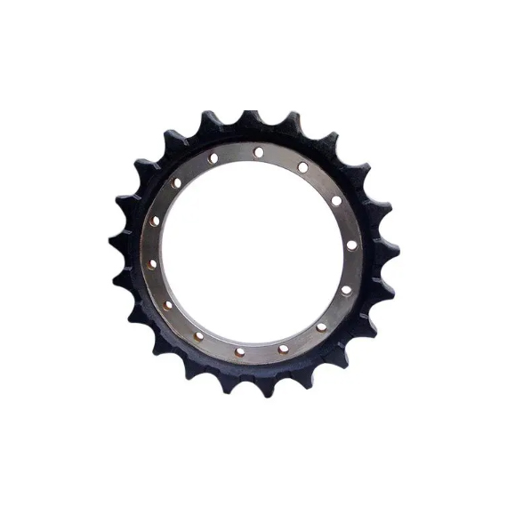
Power Transfer: The Excavator Drive Sprocket and Final Drive
The excavator drive sprocket engages the track chain to propel the machine. It sits bolted directly to the final drive hub. The heavy steel teeth pull the track links to create forward or reverse movement. Evaluating sprocket tooth wear requires a strict decision framework. Look for sharpening, cupping, or leaning on the gear teeth. Pointy teeth indicate severe material loss. As the track chain wears, the internal pins and bushings grind against each other, causing the chain pitch to extend. This pitch extension forces the sprocket teeth to catch the bushings off-center, accelerating wear on the tooth tips.
Running new chains on worn sprockets poses severe mechanical risks. The worn pitch mismatch will rapidly destroy the new chain bushings. The sprocket teeth will grind against the bushings, accelerating wear exponentially. You must always replace sprockets when installing new track groups to maintain proper pitch alignment.
Sprocket Wear Indicator
Mechanical Cause
Required Action
Sharp or Pointed Teeth
Advanced pitch extension in the track chain
Replace sprocket and evaluate track chain for replacement
Deep Cupping on Tooth Root
Abrasive material packing in the track chain
Clean tracks daily; replace sprocket if cupping exceeds 3mm
Check idler alignment and replace worn rock guards
Ground Contact: Excavator Track Shoes and Link Assemblies
Track chains consist of forged links, hardened pins, and heavy-duty bushings. They press together under immense pressure to create the continuous track rail. The excavator track shoes bolt directly onto these links. They provide essential traction, flotation, and protection for the chain beneath. Proper installation requires the turn-of-nut method, where bolts are torqued to a specific value and then rotated an additional 120 degrees to stretch the bolt and maintain clamping force.
Assess the trade-offs between sealed-and-lubricated tracks (SALT) and standard sealed tracks. SALT systems retain internal oil to eliminate pin and bushing friction. A polyurethane seal keeps the oil inside the pin cavity. They excel in high-travel applications where internal wear usually dictates track life. Standard sealed tracks rely solely on grease and heavy-duty seals. They suit low-travel, high-impact environments better, such as forestry or demolition, where debris might tear the seals of a SALT system and drain the oil.
Weight Bearing: Track Rollers and Carrier Rollers
Bottom track rollers bear the entire dynamic weight of the machine. They guide the track chain along the ground and distribute the load across the track frame. Track frames utilize a mix of single-flange and double-flange rollers. These alternate along the bottom of the frame to keep the track chain perfectly centered. Top carrier rollers support the track chain's return arc. They prevent the heavy chain from sagging and hitting the upper frame structure.
Roller flange wear presents a serious implementation risk. Worn flanges allow the track to snake, wander, and eventually derail. Internal seal failure causes lubricating oil leakage. Without oil, rapid bearing destruction follows within hours of operation. Seized rollers drag against the chain links, creating flat spots and accelerating wear across all excavator undercarriage components. When a roller seizes, the friction generates immense heat, which can compromise the heat treatment of the track links.
The Tensioning System: Front Idler (Guide Wheel), Recoil Spring, and Track Adjuster
These three components work in unison to maintain correct track tension. The front idler guides the track chain in and out of the ground contact zone. It ensures the links align perfectly with the bottom rollers. The recoil spring absorbs massive frontal shock loads when the machine strikes a stump or boulder. It sits pre-loaded under immense pressure inside the track frame.
The track adjuster uses a grease-filled cylinder to push the idler forward. Pumping grease into the valve extends the cylinder, tightening the track. A mechanical failure cascade happens if the recoil spring loses tension or breaks. The guide wheel misaligns, causing immediate track derailment. If the grease valve in the track adjuster fails, tension drops instantly. The chain will slip off the idler and sprocket, leaving the machine stranded. Packing mud into the track frame artificially increases track tension, which can blow out the grease valve or compress the recoil spring to its maximum limit, transferring all shock loads directly into the final drive.
Maintenance Cycles and Daily Status Monitoring
Critical daily maintenance extends component lifespan significantly. Operators must execute inspection routines before starting the engine. Clear packed mud, rocks, and debris from the tracks daily. Hardened mud tightens the track artificially, causing severe chain stretching and stress on the final drive. Monitor the status of sprockets and rollers for uneven wear patterns.
Inspect track tension by placing a straight edge over the top rollers and measuring chain sag in the center.
Check for leaking oil around the internal seals of bottom and top rollers.
Examine sprocket teeth for sharp edges or deep cupping.
Verify all track shoe bolts remain torqued to factory specifications.
Clean debris from the recoil spring housing to ensure it can compress freely.
Look for shiny spots on roller flanges, indicating track misalignment.
Inspect the rock guards for bending or excessive wear.
Matching Configurations to Construction Equipment Applications
Frame selection dictates machine capability and stability. Long Crawler (LC) frames provide improved stability and greater lifting capacity. Their extended footprint prevents tipping during heavy side-loading and large bucket extensions. Standard frames offer superior maneuverability in tight urban spaces and easier transportability on standard lowboy trailers. High and Wide (HW) configurations elevate the machine for forestry work, clearing high stumps and deep brush without damaging the lower carbody. Heavy-Duty (HD) frames feature reinforced plating, thicker steel, and heavy-duty rock guards for mass excavation. They withstand aggressive rock impacts and highly abrasive materials found in quarries.
Track Shoe Selection Framework
Matching shoe width to specific construction equipment applications prevents unnecessary stress on the machine. Overly wide shoes on hard rock cause bending, cracking, and extreme pin wear due to leverage forces. Narrow shoes sink rapidly in soft mud, reducing clearance and mobility. The general rule in the field is to use the narrowest shoe possible that still provides adequate flotation for the specific job site.
Grouser Type
Primary Benefit
Ideal Application
Single Grouser
Maximum penetration and aggressive traction
Hard rock, frost, and severe terrain
Double Grouser
High traction with reduced turning resistance
Forestry, demolition, and rough terrain
Triple Grouser
Balance of traction and turning ability
General construction and standard dirt work
Flat / Rubber Pads
Surface protection and low vibration
Urban streets, concrete, and asphalt
Swamp Pads (Apex)
Maximum flotation and minimal ground pressure
Marshes, bogs, and extremely soft mud
Procurement Strategy: Sourcing Construction Machinery Wear Parts
OEM vs. High-Tier Aftermarket Standards
Sourcing construction machinery wear parts requires strict adherence to metallurgical standards. Evaluate Rockwell hardness ratings and induction hardening depth. Deep heat treatment ensures the steel resists abrasion over thousands of hours of operation. The core of the steel must remain ductile to absorb impact, while the outer surface must be hardened to resist friction. If the core is too hard, the part becomes brittle and shatters under shock loads.
Substandard steel alloys pose massive operational risks. They suffer premature cracking under high-impact conditions, leading to sudden failures. High-tier aftermarket parts often match or exceed OEM specifications by utilizing advanced boron steel alloys. Always demand material test reports and warranty documentation before purchasing bulk components for a fleet. Verify the quenching and tempering processes used by the manufacturer to ensure consistent wear rates across the entire track group.
Navigating a Heavy Equipment Spare Parts Catalog
Consulting a heavy equipment spare parts catalog requires technical precision. Fleet managers must verify part numbers, pitch measurements, and bolt-hole patterns accurately. A single mismatched dimension halts installation and wastes valuable shop time. Manufacturers frequently update designs mid-production, meaning a machine built in January might use different rollers than the exact same model built in October.
Measure the exact chain pitch with specialized calipers to ensure sprocket compatibility.
Count the exact number of track links to order the correct chain length.
Verify the inner and outer flange dimensions on bottom rollers.
Confirm the final drive bolt-hole configuration and diameter.
Check the machine serial number breaks to ensure exact fitment.
Weigh the upfront cost of individual components against the labor cost and downtime of a complete undercarriage overhaul. A complete replacement saves money compared to piecemeal repairs. Replacing one part often accelerates wear on older mating parts, forcing you to tear down the track system multiple times. Installing a new track chain on worn rollers will rapidly destroy the new chain links.
Conclusion
Conduct a standardized wear measurement using ultrasonic testing or specialized calipers on all track components every 500 operating hours.
Clean the track frames daily with a specialized track spade or pressure washer to prevent mud packing and subsequent chain stretching.
Consult a technical parts specialist to map out a proactive replacement schedule based on your specific site wear rates and soil conditions.
Replace sprockets and track chains simultaneously to prevent mismatched pitch wear and immediate bushing destruction.
FAQ
Q: How often should an excavator undercarriage system be inspected?
A: Operators must perform daily visual checks before starting the machine. This includes clearing debris and checking for loose hardware. Fleet managers should schedule comprehensive wear measurements using calipers or ultrasonic tools every 500 operating hours to track component degradation accurately.
Q: What causes an excavator track to derail?
A: Derailment typically stems from incorrect track tension. If the chain is too loose, it slips off the idler. Worn front idlers, misaligned guide wheels, or severe roller flange wear also allow the track chain to snake and jump off the track frame during turns.
Q: When should I replace my excavator drive sprocket?
A: Replace the sprocket when the teeth become sharp, pointed, or cupped. Visual indicators of severe wear mean the pitch no longer matches the chain. You must always install new sprockets when fitting a new track chain to prevent rapid bushing destruction.
Q: How do you adjust the tension on an excavator track?
A: You adjust tension using the track adjuster mechanism. Pumping grease into the adjuster cylinder pushes the front idler forward, tightening the chain. To loosen the track, slowly open the grease bleed valve to release pressure, allowing the idler to retract.
Q: What is the difference between sealed and lubricated track chains?
A: Standard sealed chains keep dirt out using basic seals and grease, making them ideal for low-travel, high-impact work. Sealed and lubricated track (SALT) chains contain internal oil reservoirs. This oil continuously lubricates the pins and bushings, significantly reducing internal wear during high-travel applications.
Q: Can I mix OEM and aftermarket undercarriage parts?
A: Yes, provided the aftermarket parts meet exact OEM specifications. You must ensure perfect pitch matching and dimensional compatibility. However, mixing new parts with severely worn parts, regardless of brand, causes uneven wear rates and accelerates the degradation of the new components.